You have selected free tutorial of the AutoDesk for the Autodesk Certified User (ACU) :
Autodesk Revit Architecture Certified User Exam - Imperial/Matric
Topics : User Interface : Interface Definition: UI Features: Autodesk Revit window, graphics window, the ribbon, project browser, and the context (right-click) menus.: Identify primary parts of the User Interface (UI). (Tabs, Application menu, Info Center, Ribbon, Elevation tag, Status bar, View control Bar
Autodesk Help:-

Application Menu
Click the big R in the upper-left corner of the UI to open the Application menu and then access commonly used commands such as New, Open, Save, Print, and so on. You can also export your project to a number of 2D and 3D formats from this menu. This menu is also where you manage licensing information. The Publish option lets you upload exported formats (DWF, DWG, DXF, DGN, and SAT) to Autodesk® Buzzsaw® to share project documents with your team. Use the Close command to quickly close a project or family without closing every open view. When accessing some of the flyout commands in the Application menu, be aware that there may be additional commands or options on the flyout that are hidden. This is most evident on the Export command flyout, in which you must scroll to the bottom of the flyout to access exporting options for IFC (Industry Foundation Classes) and others.
Quick Access Toolbar
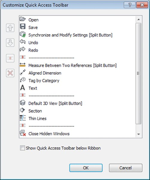
The Quick Access toolbar (QAT) allows you to keep frequently used tools at your fingertips. Some commonly used commands are included by default in the QAT, but you can customize it to meet your own needs. Right-click any button in one of the ribbon tabs, and you will find the command Add To Quick Access Toolbar. By clicking the small, down-facing arrow to the far right of the QAT, you’ll find that tools may be further customized, grouped, or removed from the toolbar (Figure below). By default, the QAT bar is above the ribbon, but you also have the option to show the QAT below the ribbon.
InfoCenter
To the far right of the QAT is the InfoCenter (Figure below).From left to right, you have the ability to search for help solutions, access the Subscription Center, open the Communication Center, show Favorites (saved articles and solutions from the Communication Center), sign in to other Autodesk services (such as cloud rendering), launch the Autodesk Exchange for Revit (Exchange Apps), and open the help content.

Ribbon
The ribbon is the primary location for accessing the commands and tools you will use in a project (Figure below). You can launch commands and tools using the ribbon, or you can create customized keyboard shortcuts as an alternative.
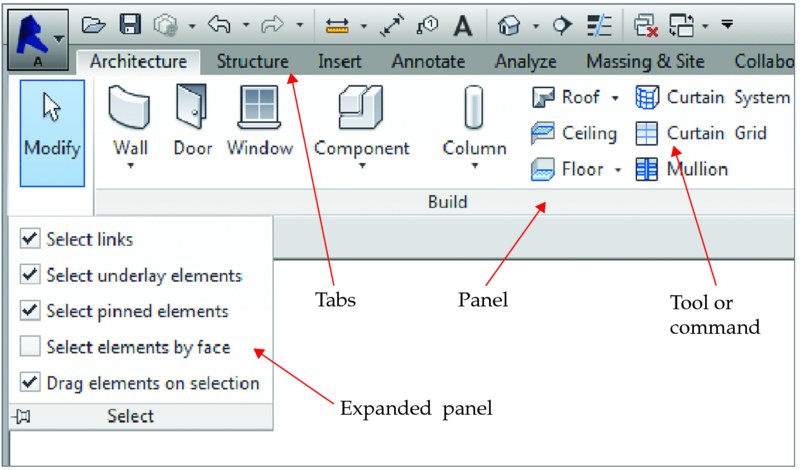
The organization and size of the icons within each panel on the ribbon will change slightly as you scale the size of your application window. As the application window gets smaller, the icons will decrease in size and will sometimes stack, or the descriptions will be hidden.
TOURING THE TABS
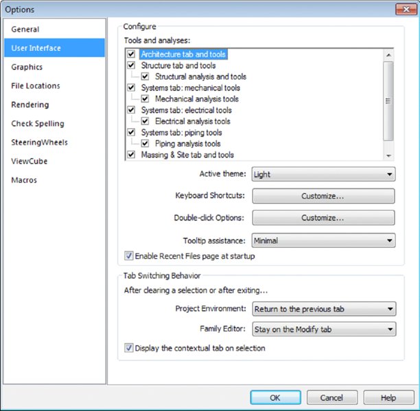
Tabs are the highest level of organization and are used to select from among the various groups of functionality. There are up to 11 tabs along the top of the ribbon. We’ll take a moment to briefly describe them: Architecture, Structure, or Systems If you install Revit Architecture you will only have access to the Architecture and Structure tabs in the ribbon. If you install Revit with one of the Autodesk Building Design suites, you will have access to the tools for all three design disciplines, and you can control the visibility of these tabs (Architecture, Structure, and Systems) from the Options dialog box (accessed from the Application menu), as shown in Figure below. These tabs contain tools you will use to create or place content specific to each design discipline
.
- Insert The Insert tab is used to link external files (2D, 3D, image, and other RVT files) as well as search for external content via Autodesk® Seek. To insert content from family files, you can use the Load Family command from this tab; however, this same command is available with most modeling commands in the contextual tab of the ribbon.
- Annotate The Annotate tab contains many of the tools necessary to annotate, tag, dimension, or otherwise graphically document your project.
- Analyze The Analyze tab contains the tools necessary to modify energy analysis settings and to run an energy simulation via Green Building Studio®. This feature requires an Autodesk Subscription account to access the online analysis engine.
- Massing & Site The Massing & Site tab contains the tools necessary to add massing- and site-related elements such as toposurfaces and property lines.
- Collaborate The Collaborate tab contains the tools that you’ll use to coordinate and manage the project within your own team as well as across other teams and their linked files.
- View The View tab contains the tools that you’ll use to create all your project views, 2D and 3D, as well as schedules, legends, and sheets. You can also modify your UI from this tab, including your keyboard shortcuts.
- Manage The Manage tab contains tools to access all your project standards and other settings. You will also find the Design Options and Phasing tools on this tab. Additional tools such as Review Warnings and Select By ID are found in the Manage tab and will help keep your project running smoothly. One of the most important settings that you’ll use during your project is Object Styles on the Manage tab. Selecting this option will allow you to manage the global visibility settings for just about everything in your project: how it projects, how it cuts, and its associated color and pen weight.
- Modify The Modify tab contains the tools used to manipulate the content that you’re creating in your project. You’ll find tools like Cut, Join, Move, Copy, and Rotate, among many others.
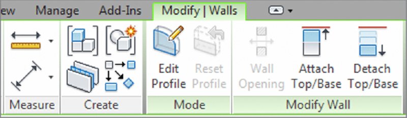
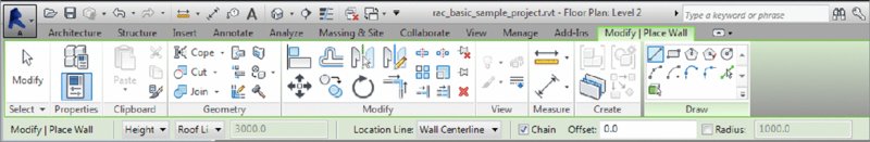
- Contextual Tabs Contextual tabs are revealed when specific elements are selected or element creation commands are launched. For example, the Modify | Walls contextual tab (Figure below) is displayed when a wall is selected. These unique tabs are usually colored green to help you distinguish them from other static tabs in the ribbon. A simple, yet important, setting that may be exposed on the contextual tab when placing model content is Tag On Placement. Modeling commands like Door, Window, and Component allow you to enable automatic tagging to reduce overall documentation time. If you are working in an early design phase, you may wish to disable the Tag On Placement setting.
OPTIONS BAR
The Options bar is located directly below the ribbon and is a contextually sensitive area that gives you feedback as you create and modify content. In Figure below, you see the options available below the ribbon when the Wall tool is active. You can also use the Options bar when an object already placed in a project or family is selected. An especially important and frequently used option is included with any annotation symbol—the ability to include or exclude a leader. This will help you place tags in the clearest location within your documentation while maintaining a parametric relationship to the associated model element. Look for this option when you use the Tag By Category command from the Annotate tab in the ribbon.
STATUS BAR
The status bar at the bottom of the UI provides useful information about selected objects and active tools. When you start a tool, the status bar will display prompts about the next step required of the tool. For example, select an object and start the Rotate command; the status bar will read "Click to enter rotate start ray or drag or click the rotation center control." It is also useful when you are using the Tab key to toggle between object snap points or when selecting chains of elements.
Toward the middle of the status bar, you will find toolbars for worksets and design options. At the far right end, you will see a filter icon next to a number. When you select objects in a view window, the number of selected objects will be displayed here. Click the Filter icon to open the Filter dialog box and refine the selection set. The five icons next to the Filter icon determine which objects in your model are eligible for selection.
DRAWING AREA
The drawing area is the window into your design space. you can tile several views from any number of open files or you can maximize the view windows. When the view windows in the drawing area are maximized, press Ctrl+Tab on the keyboard to cycle through the open views. To reverse the cycling, press Ctrl+Shift+Tab.
View Control bar